
Multiphase Flow Laboratory
Operational capabilities - Multiphase flow laboratory
Contact persons
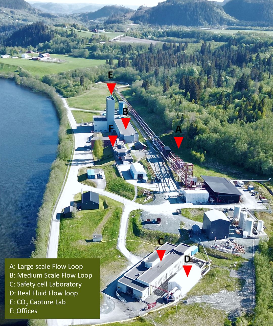
The Large scale loop
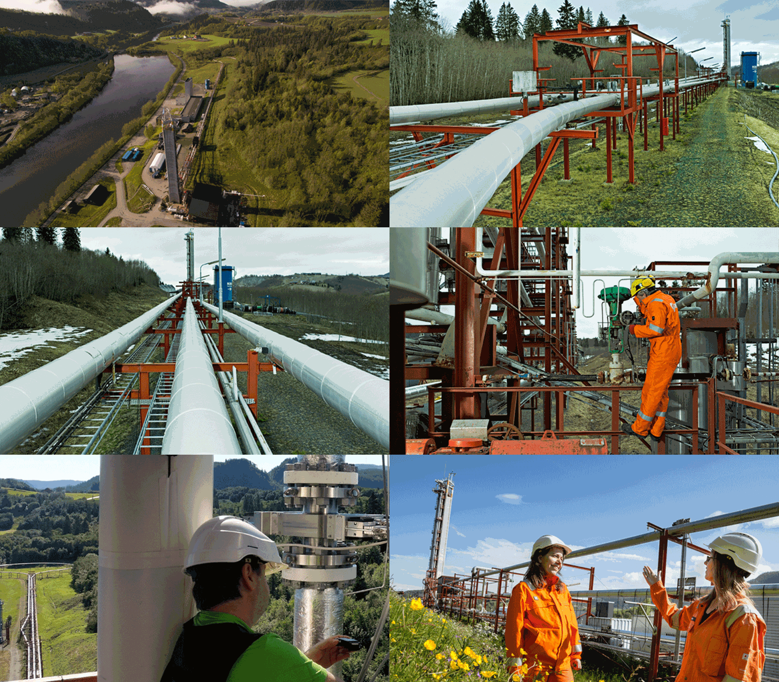
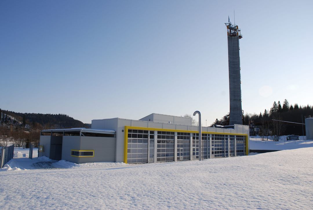
The Large Scale Loop is an industrial-sized three-phase flow laboratory. The capabilities cover a wide range of industry conditions to allow studies of all major flow challenges during production.
This test facility, the largest of its kind, has been the foundation for development in subsea oil and gas production in cold environments and over long transportation distances (See the film). The facility process equipment allows flexibility to accommodate customized testing geometries that differ to the standard pipe configuration.

Technical specifications
|
Large Scale Flow Loop |
|
| Operating pressure | 5 – 90 barg |
| Operating temperature | 10 – 50°C |
| Flow rate, gas | 2 – 1500 m³/h |
| Flow rate, oil | 0 – 480 m³/h |
| Flow rate, water | 0 – 200 m³/h |
| Gas phase | Nitrogen (any inert gas) |
| Oil phase | Any clean oil, up to 200 cP |
| Water phase | Tap water, brine |
| Near horizontal pipe length (0 to 2.5°) | 800 m |
| Pipe sizes | 8" typically; 4" to 12" available |
| Material | Carbon steel |
Instrumentation:
- Flow rates
- Temperature
- Pressure
- Flow visualization
- Phase densities
- Phase fractions in the test section
- Available advanced instrumentation
Services:
- Detailed multiphase flow in transport lines, wells and risers
- Independent third- party verification and testing of equipment and sensors (Separators, pumps, valves, DTS, DAS, phase meters)
- Evaluation of fluid properties effect in the flow (Viscosity, Density, surface tension)
- Design of custom facilities
The medium scale loop
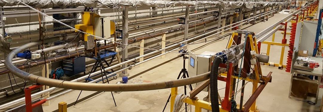
The Medium Scale Loop is located indoor in a 60 m long laboratory hall. This is a 3-phase flow test facility that includes an 11 m³ separator that provides long retention times so that less easily separable fluids, such as viscous oils can be used. In addition by using SF6 as the gas phase, gas densities equal to that of methane at 88 bar can be reached. The use of crude oils with flash point higher than ambient temperature can be tested allowing testing closer to field conditions.
This facility allows the study of multiphase flow in much greater detail than what is possible in the Large Scale Loop. For example: oil droplets, gas entrainment into oil and droplet entrainment into the gas phase, may be studied in this facility.
The testing geometry is decided by the client within the loop capacity.
Technical specifications
|
Medium Scale Flow Loop |
|
| Minimum operating pressure | atm. |
| Operating temperature | 5 – 50°C (20) |
| Flow rate, gas | 5 – 160 Am³/h |
| Flow rate, oil | 0.1 – 80 m³/h |
| Flow rate, water | 0.1 – 120 m³/h |
| Gas phase | (any inert gas) |
| Oil phase | Exxol D80 (any non-flammable HC) |
| Water phase | Fresh water, brine |
| Near horizontal pipe length | Up to 200 m |
| Inclinations | -4 to 4° |
| Pipe sizes | Ideal size 3"; 2.5" to 5" available |
| Vertical pipe length | 35 m |
| Material | Stainless steel |
Measurements:
- Flow rates
- Temperature
- Pressure
- Flow visualization
- Phase densities
- Phase fractions in the test section
- Phase fractions profile in the separator
- Available advanced instrumentation
Services:
- Detailed multiphase flow in transport lines and wells
- Independent third- party verification and testing of equipment and sensors (i.e. Separators, pumps, valves, DTS, DAS, phase meters)
- Evaluation of fluid properties effect in the flow (Viscosity, Density, surface tension)
- Design of custom facilities
Large high pressure vessel
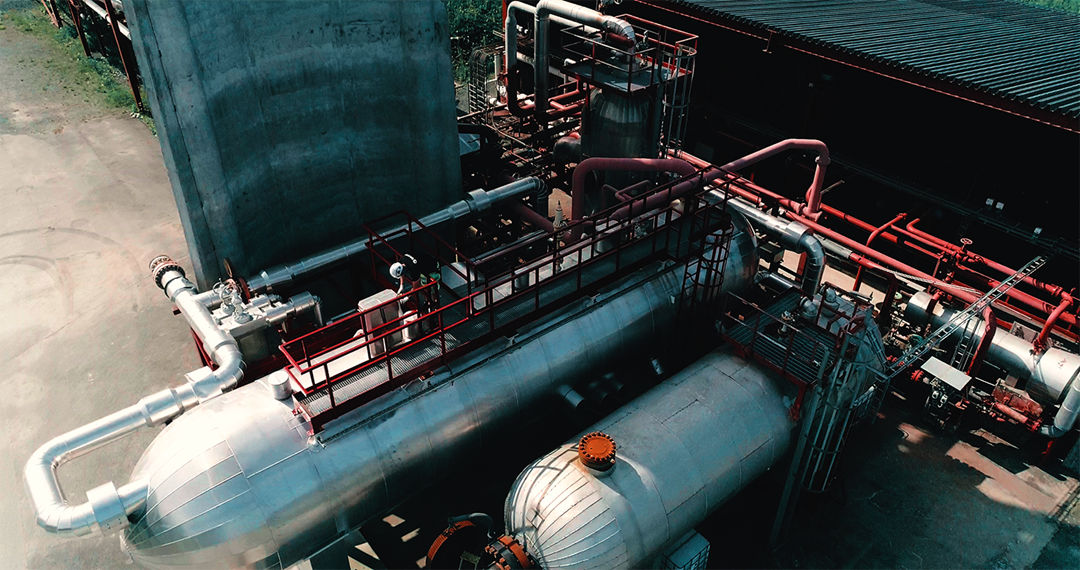
The laboratory has available a large, high-pressure vessel. It can be used for applications where a high-pressure reservoir of gas or liquid is needed. Typical use is single-pass flow tests with large pressure differences. Such tests span a very large range from long-duration gas tests to short high-flow tests.
The vessel is certified to be used with flammable gases and liquids (in 2021); both water and hydrocarbons. It can be readily charged with nitrogen, dry CO2 or natural gas from gas supply facilities exisiting on the premises.
The vessel is equipped with blow-down valve and overpressure protection valve.
The vessel is insulated with 80 mm mineral wool and is heat traced.
Technical specifications
|
Vessel data |
|
| Volume | 32,9 m³ |
| Max operating pressure | 97,5 barg |
| Design temperature | -25 °C to 82 °C |
| Material | Carbon steel |
| Flow rate, water | 0.1 – 120 m³/h |
| Connections (all 900 lbs RTJ) | 2 x 24" (Manways), 2 x 12", 3 x 3", 2 x 2" |
High pressure gas supply facility
The laboratory has available a high ressure gas supply facility. It can be used supply natural gas/methane, CO2, nitrogen or argon up to 250 bar.
The facility is typically used as part of other infrastructure that requires the supply of large gas volumes (larger than 500 kg).
Technical specifications
|
Facility data |
|
| Supply rate | 4.5 l/min |
| Storage vessel volume | 6 m³ |
| Gas supply pressure | -up to 250 bar. |
The safety cells
The laboratory for experiments that are explosive and poisonous. Different setups can be built within the Safety cells. Some of the features of the cells are:
- Safe drain and vent
- Gas detection
- Temperature controlled chambers
- Instrumentation and logging infrastructure
- Gas distribution
- Chemistry laboratory
- Control rooms
Recent experimental work using the facilities
- Crude oil hydrate experiments and emulsion experiments
- Experiments with H2S exposure
- CO2/NG membrane separation experiments
The wheel flow loops
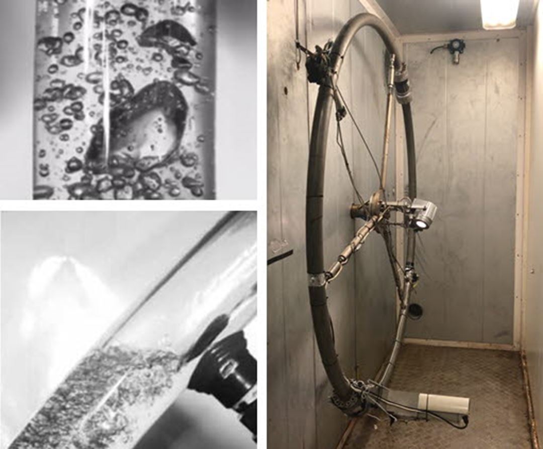
This test facility consists of a steel pipe manufactured as closed hoop. The wheel is installed in vertical orientation and mounted on a shaft, which is rotated by an engine. The flow is driven by gravity, thus no pump or compressor is required. The fluids inside the wheel "see" an endless pipe through which they flow as multiphase mixture. All wheels are equipped with a torque sensor. Visual observation is possible for individual wheels. Placed in a climate chamber, temperature can be controlled precisely.
Services:
- Screening of production chemicals (Such as hydrate inhibitors, demulisifiers, drag reducers)
- Hydrate management: Long-term evalaution of plugging risk or deposition under restart, shut-in or transport situations
- Study of timescales for flow development (formation and separation of emulsions)
- Study of stability of drilling fluids (realistic PVT)
Measurements:
- Temperature
- Pressure
- Flow visualization
- Velocity
- Torque
The high pressure cell
This test facility consists of an autoclave made with titan grade 2 and a sapphire cell. The cell has an inside cell volume of 200 ml. The high pressure cell has traditionally be used to provide an easy and fast way to understand the risk of hydrate agglomeration.
Fluid group: flammable gasses and liquids (e.g crude oil (or condensate), natural gas, H2), CO2 (with impurities) or water.
Technical specifications
|
Facility data |
|
| Working temperature | -10C to 150 C |
| Working pressure | 250 bar |

