
BIGCCS - International CCS Research Centre
CO2 Capture
Contact person
Solvent technology
Overall objective:
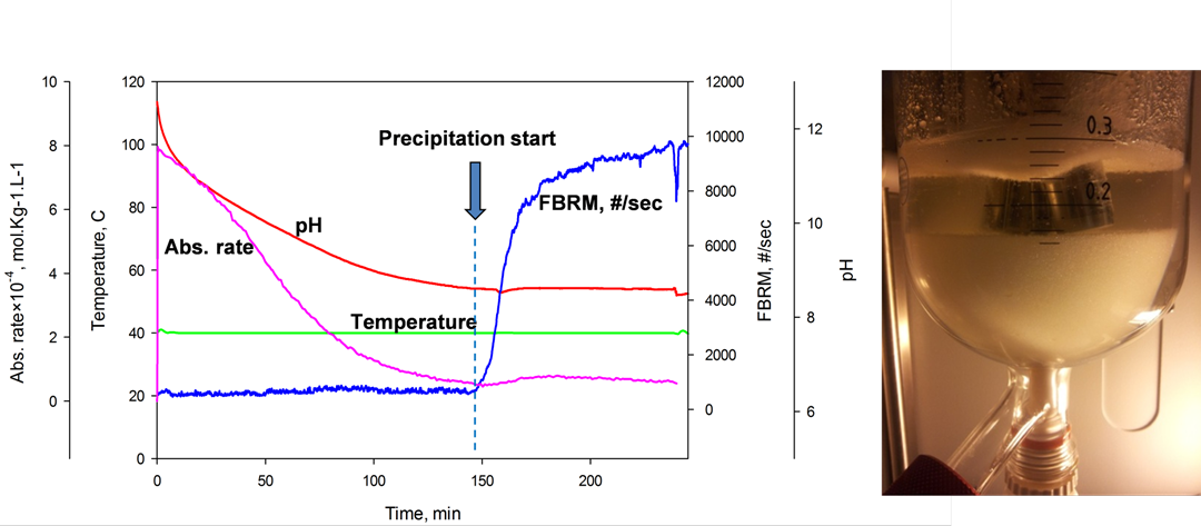
To enhance CO2 capture efficiency by increasing cyclic capacity through solvents engineered into liquid-solid phase change in the presence of CO2 at process conditions and to develop a dynamic model to be used for evaluation of solvents under transient conditions.
Contribution to one or more of the overall goals/objectives of BIGCCS
A tangible objective of BIGCCS is 50% reduction of CO2 capture cost; increased cyclic capacity of CO2 absorbent is directly coupled to capture cost reduction. Dynamic model of a capture process will enhance the reliability. This task contributes to the scientific and technological objective of BIGCCS by knowledge development through high quality research which has been disseminated through conferences and journal publications. This task currently hires a PhD candidate in line with the recruitment objective of BIGCCS.
Achievements thus far
- Absorbents that improve capture efficiency due to precipitation at process condition have been identified. Characterization studies have been carried out on the precipitate and the precipitating systems. Initial results have shown that precipitation at process condition results to significant reduction in energy number.
- A dynamic process flowsheet model has been developed in Matlab and also linked to the CO2SIM (SINTEF in-house simulation tool for absorption based processes) framework. Dynamic pilot plant campaign is being concluded.
Innovative membrane technologies
Overall objective:
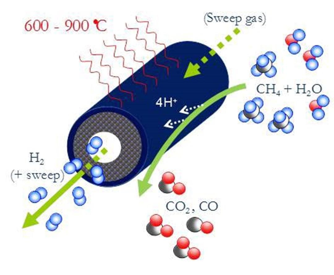
To develop dense inorganic membranes for pre-combustion decarbonisation processes, e.g., steam-methane reforming, and hybrid membranes for post-combustion CO2 separation.
Contribution to one or more of the overall goals/objectives of BIGCCS
The membrane technologies investigated are core components in several of the pursued CO2 capture schemes. Therefore, membrane performance in terms of flux, selectivity and stability under realistic operation conditions directly address the overall project goals related to capture rate, cost reduction and fuel-to-electricity efficiency.
Task 1.2 achievements thus far
- State-of-the-art materials developed for Hydrogen Transport Membranes (HTM) and Oxygen Transport Membranes (OTM)
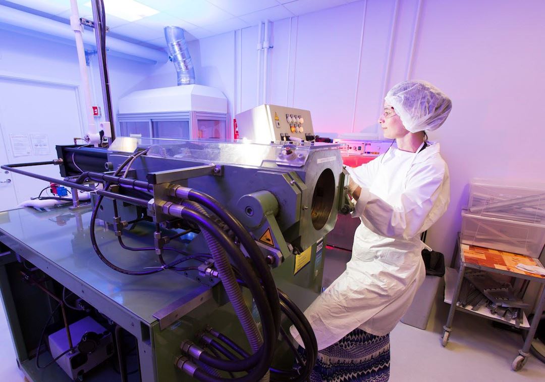
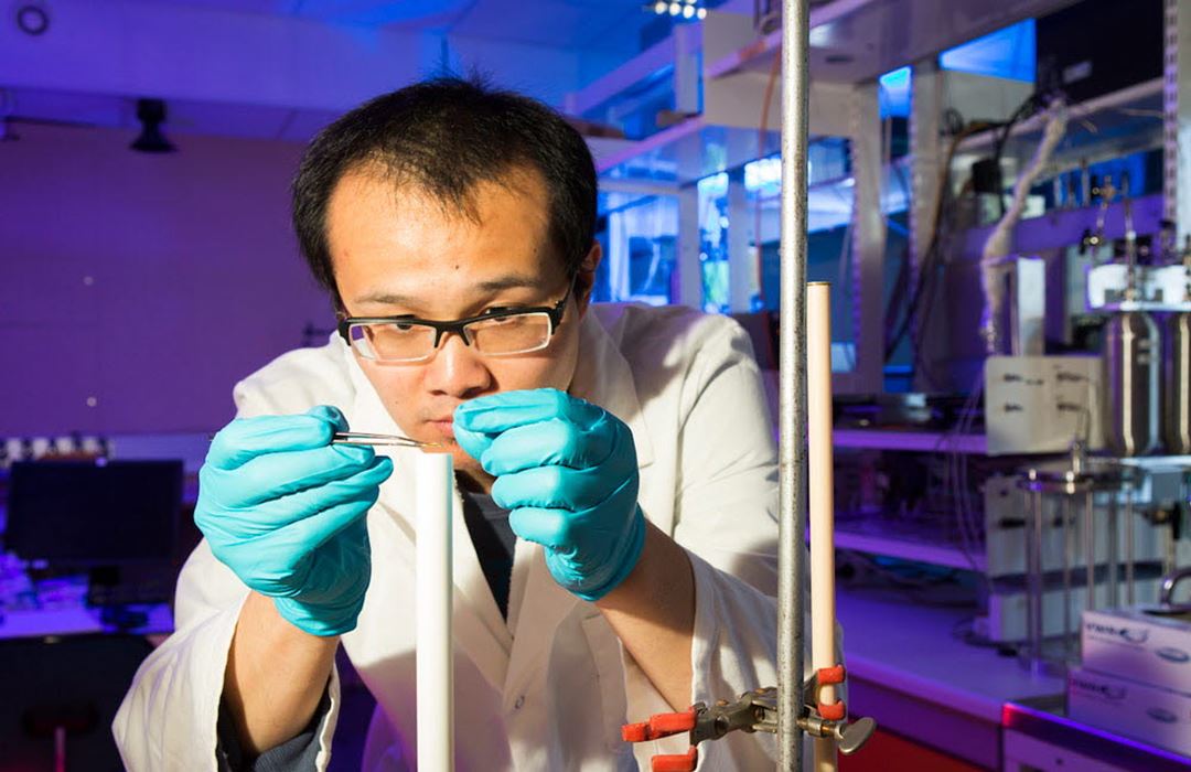
- Fabrication of asymmetric tubular OTM and HTM, 30-50 cm long
- Attained fundamental understanding of the mechanisms governing the hydrogen production rate in HTM
- Asymmetric tubular OTM successfully tested with stable flux for > 200 hours
Related publications
- CO2 removal at high temperature from multi-component gas stream using porous ceramic membranes infiltrated with molten carbonates
Fontaine, M. L. Peters, T. A. McCann, M. T. P. Kumakiri, I. Bredesen, R. | | 2013 -
Investigation of La0.87Sr0.13CrO3−∂ as membrane for hydrogen production
Larring, Y. Vigen, C. Ahouanto, F. Fontaine, M.-L. Peters, T. Smith, J. B. Norby, T. Bredesen, R. | | 2012
Hydrogen Combustion Technologies
The overall objective of the task is to provide clean and efficient solutions for CO2 capture technologies based on combustion of hydrogen and hydrogen-rich synthetic gaseous fuels
Task 1.3 contributes to the overall objectives of BIGCCS through:
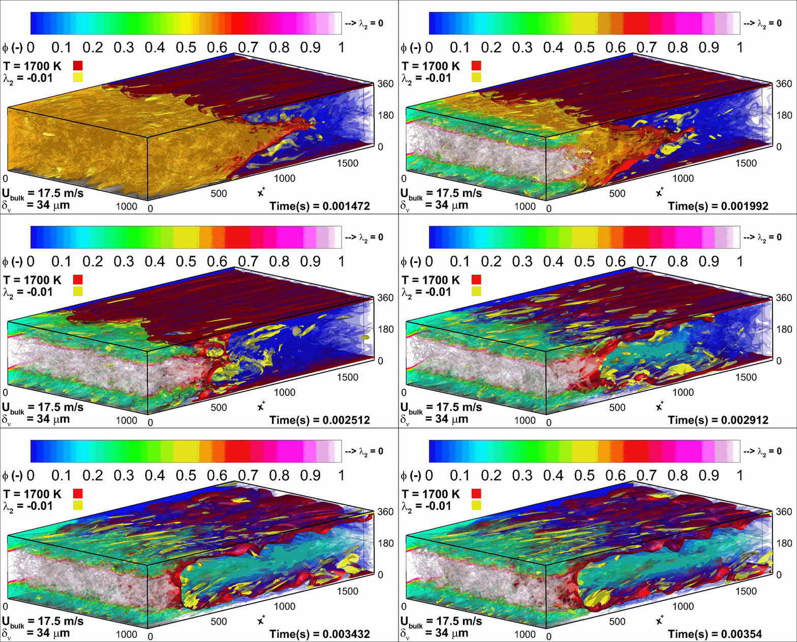
- Advancement in the fundamental understanding of the physical processes that characterize combustion of hydrogen, including flame propagation and pollutant formation, at both laminar and turbulent conditions, as opposed to combustion of more conventional gas turbine fuels (natural gas, fuel oil).
- Optimization of the hydrogen fuel injection method and of its mixing pattern within the oxidant stream, while still conserving operational safety and fuel efficiency.
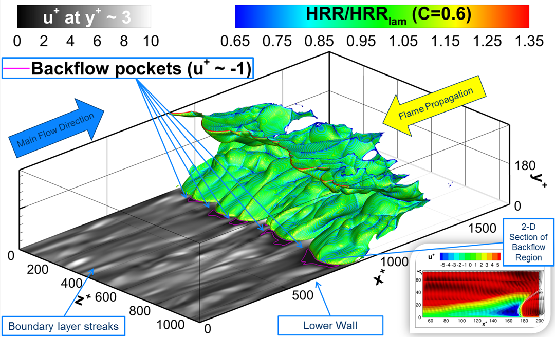
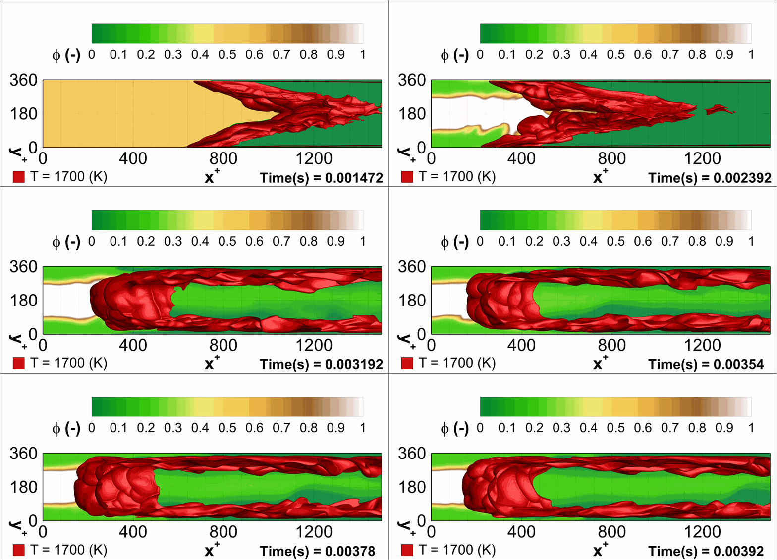
- Acquisition of detailed knowledge about flame propagation and stabilization characteristics, with specific focus on flashback (upstream flame propagation against the direction of the main reactant’s flow), for hydrogen-air flames.
- The close collaboration with world-renowned combustion research groups at Sandia National Laboratories (Livermore, California), DLR (Stuttgart, Germany), TU Munich (Munich, Germany) and Princeton University (Princeton, New Jersey) strengthen considerably the scientific level and the international visibility of the research performed within the task.
Addressing point 1) is of fundamental importance to improve the confidence in the utilization of hydrogen-rich mixtures as main fuel for large-scale, clean and highly efficient power generation with minimal CO2 footprint. Solving the issues related to point 2) and 3) above will enable the deployment of pre-combustion CO2 capture schemes based on new, highly efficient (no fuel dilution with N2 required!) hydrogen combustion equipment for gas turbine engines.This is a necessary step within the pre-combustion route to CCS because using existing combustion equipment is presently hindered by the peculiar combustion properties of hydrogen (high reactivity, high diffusivity) compared to more traditional hydrocarbon fuels, for which existing equipment has been designed.
Task 1.3 achievements so far:
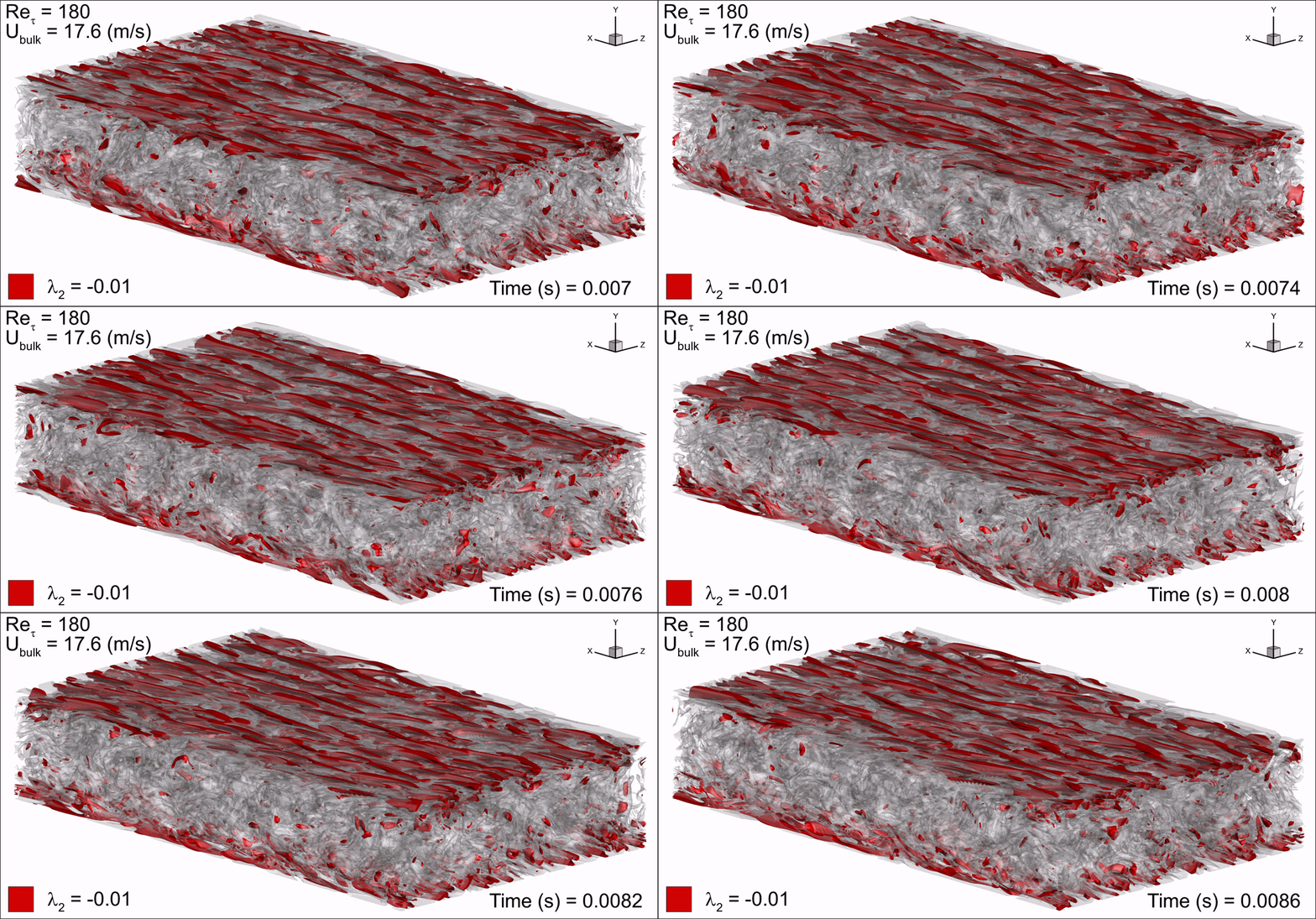
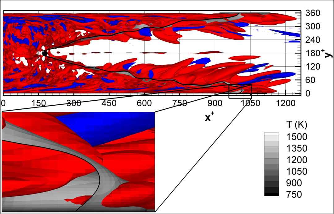
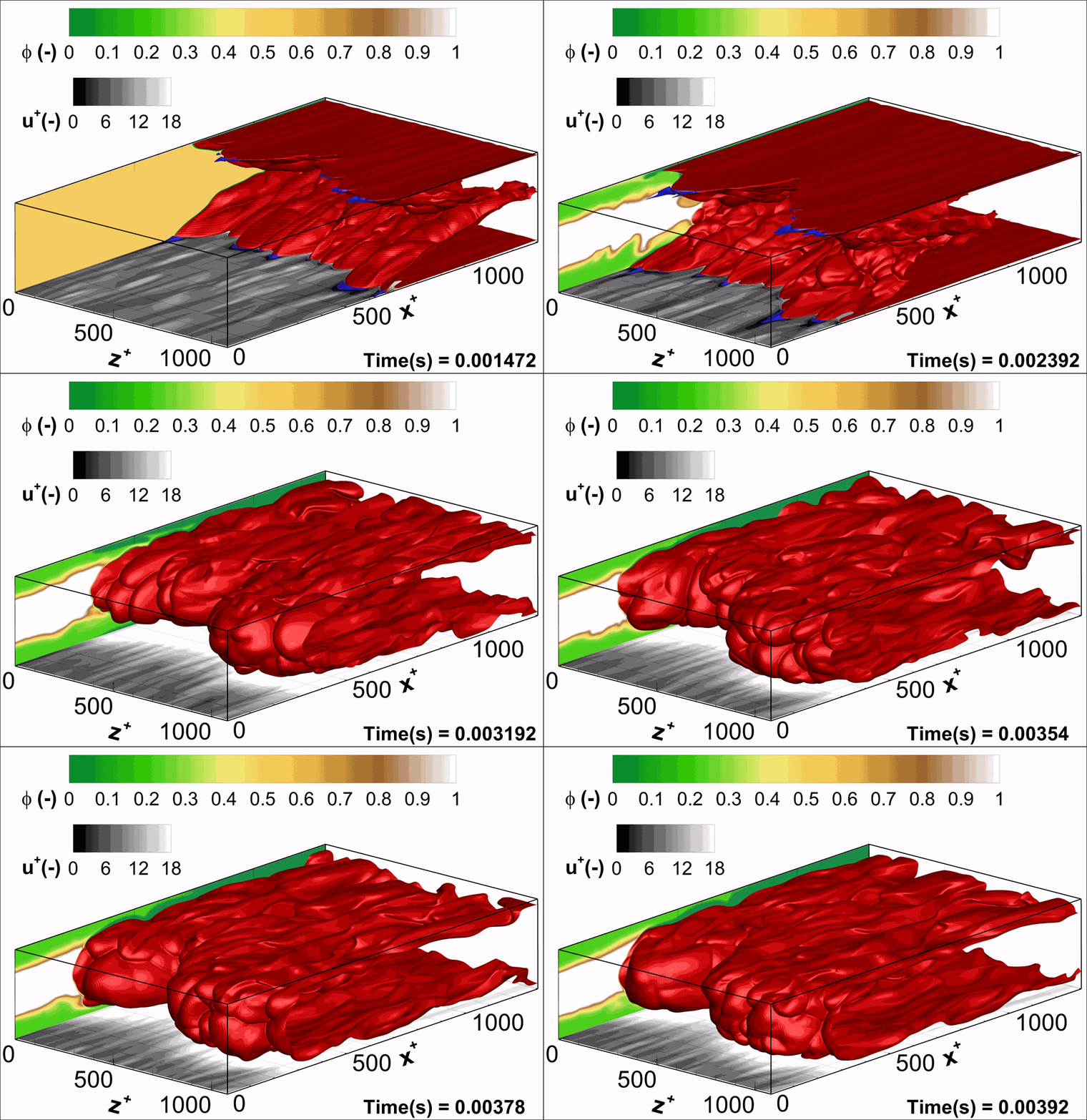
- Flashback of hydrogen-air turbulent flame in ducts is characterized, using Direct Numerical Simulation (SINTEF/Sandia NL) and high-definition laboratory experiments (TU Munich), a previously unknown feature of near-wall flame propagation is discovered and severe limitations of a widely used boundary layer flashback model from Lewis and Von Elbe are exposed.
- A novel analytic flame channel-flashback model is proposed and validated (SINTEF/Sandia NL).
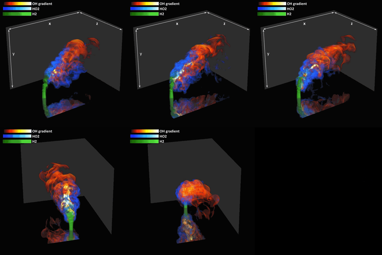
- A new fuel injection device, based on a porous steel support, a H2-selective membrane and a ceramic diffusor layer, is being investigated, both numerically and experimentally, in order to solve well-known issues related to hydrogen injection through conventional fuel injection methods (nozzles) and the concentrated point sources of the highly reactive fuel species (SINTEF/DLR).

Related publications
- Experimental Investigation of a Bluff Body Burner for Distributed Hydrogen Injection
Gounder, J.D.; Kutne, P.; Gruber, A. | ASME Turbo Expo 2017: Turbomachinery Technical Conference and Exposition - Volume 4A: Combustion, Fuels and Emissions Charlotte, North Carolina, USA, June 26–30 | 2017 - Prediction of Confined Flame Flashback Limits Using Boundary Layer Separation Theory
Hoferichter, V.; Hirsch, C.; Sattelmayer, T. | Journal of Engineering for Gas Turbines and Power, Vol. 139 (2), 021505 | 2017 - Experimental Investigation of the Transition Mechanism from Stable Flame to Flashback in a Generic Premixed Combustion System with High-Speed Micro-Particle Image Velocimetry and Micro-PLIF Combined with Chemiluminescence Imaging
Baumgartner, G.; Boeck, L.R.; Sattelmayer, T. | Journal of Engineering for Gas Turbines and Power, Vol. 138(2), 021501 | 2016 - Identifying turbulent structures through topological segmentation
Bremer, P.-T.; Gruber, A.; Bennett, J.C.; Gyulassy, A.; Kolla, H.; Chen, J.H.; Grout, R.W. | Communications in Applied Mathematics and Computational Science, Vol. 11(1), pp. 37-53 | 2016 - Effect of fuel composition and differential diffusion on flame stabilization in reacting syngas jets in turbulent cross-flow.
Minamoto, Y.; Kolla, H.; Grout, R.W.; Gruber, A.; Chen, J.H. | Combustion and Flame, vol. 162(10), pp. 3569-3579 | 2015 - Modeling of mean flame shape during premixed flame flashback in turbulent boundary layers
Gruber, A.; Kerstein. A.; Valiev, D.; Law, C. K.; Kolla, H.; Chen, J. H. | Proceedings of the Combustion Institute, vol. 35 (2), pp. 1485–1492 | 2015 - Direct numerical simulation of laminar flame-wall interaction for a novel H2-selective membrane/injector configuration
Gruber, A.; Salimath, P. S.; Chen, J. H. | International Journal of Hydrogen Energy, vol. 39, pp. 5906-5918 | 2014 - Large Eddy Simulation of premixed flame flashback in a turbulent channel
Lietz, C.; Hassanaly, M.; Raman, V.; Kolla, H.; Chen, J. H.; Gruber, A. | 52nd AIAA Aerospace Sciences Meeting - AIAA Science and Technology Forum and Exposition, SciTech 2014 | 2014 - Influence of burner material, tip temperature, and geometrical flame configuration on flashback propensity of H2 air jet flames
Duan, Z.; Shaffer, B.; McDonell, V.; Baumgartner, G.; Sattelmayer, T. | Journal of Engineering for Gas Turbines and Power, Vol. 136(2) 021502 | 2014 - Fundamental modeling of a membrane reactor with in-situ hydrogen separation and combustion
Weydahl, T.; Salimath, P. S.; Gruber, A. | Energy Procedia, vol. 37, pp. 2341–2348 | 2013 - Direct numerical simulation of premixed flame boundary layer flashback in turbulent channel flow
Gruber, A.; Chen, J. H.; Valiev, D.; Law, C.K. | Journal of Fluid Mechanics, vol. 709, pp. 512-542 | 2012 - A direct numerical simulation study of turbulence and flame structure in transverse jets analysed in jet-trajectory based coordinates
Grout, R. W.; Gruber, A.; Kolla, H.; Bremer, P.-T.; Bennett, J. C.; Gyulassy, A.; Chen, J. H. | Journal of Fluid Mechanics, vol. 706, pp. 351-383 | 2012 - Premixed flame flashback in wall boundary layers studied by long-distance micro-PIV
Eichler, C. and Sattelmayer, T. | Experiments in Fluids, vol. 52, pp. 347–360 | 2012 - Experimental investigation of turbulent boundary layer flashback limits for premixed hydrogen-air flames confined in ducts
Eichler, C.; Baumgartner, G.; Sattelmayer, T. | Journal of Engineering for Gas Turbines and Power 134(1), 011502 | 2011 - Turbulent flame–wall interaction: a direct numerical simulation study
Gruber, A.; Sankaran, R.; Hawkes, E. R.; Chen, J. H. | Journal of Fluid Mechanics, vol. 658, pp. 5-32 | 2010
Oxy-Fuel Technologies
The overall objective of the task is to provide solutions for Oxy-fuel combustion and Flue Gas Recirculation based CO2 capture technologies
Task 1.4 contributes to the overall objectives of BIGCCS through:
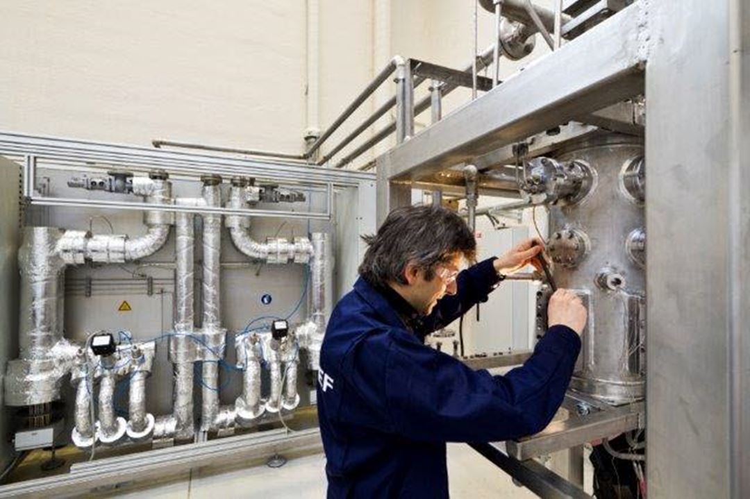
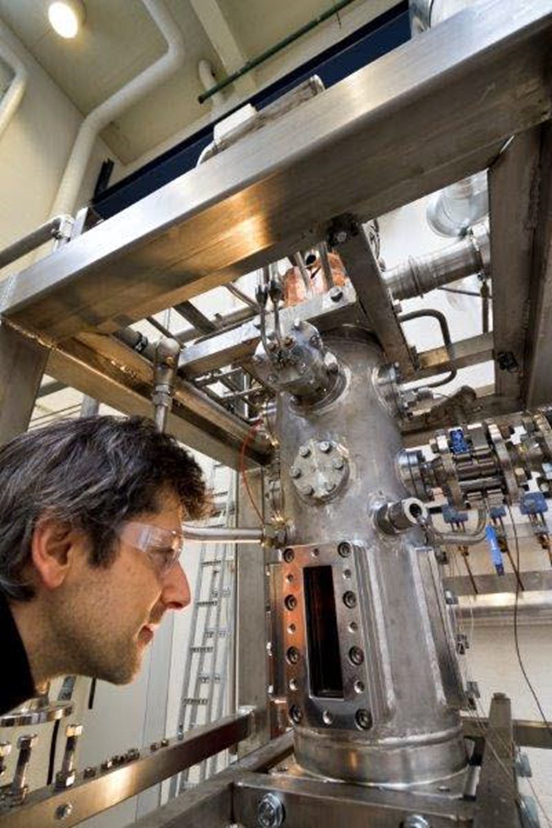
- The installation of the high pressure oxyfuel combustion facility (HIPROX), a powerful experimental platform for the creation of new oxy-fuel burners and combustors, as well as an international site for testing equipment through the EU research infrastructure sharing program ECCSEL.
- The conception and study of thermal power cycles with exhaust gas recirculation (EGR or FGR) to reach concepts with fuel-to-electricity penalty less than 6 percentage points compared to state-of-the-art fossil fuel power generation.
- The collaboration with research groups: DLR (Stuttgart, Germany) and Målardalen University (Sweden) strengthening the international cooperation within the field of CCS.
- The study of innovative burner and flame technologies, such as MILD combustion, providing crucial knowledge and a basis for technology breakthroughs.
Some Task 1.4 achievements:
- Fully operative high pressure oxy-fuel combustion facility (HIPROX).
- Demonstration of the FLOX® concept for flue gas recirculation (FGR) cycles (DLR/Stuttgart).
- A supplementary fired unit cycle configuration that has achieved an efficiency penalty less than 6 %.
- Benchmarking evaluation of Exhaust Gas Recirculation (EGR) technologies applied to post-combustion cycles.
- Spin-off of a pilot scale oxy-fuel gas turbine project OXYGT with Siemens, NEBB Engineering and Lund University.
- Characterization of heat radiation and soot formation in oxy-fuel flames.
- New fundamental knowledge acquired in Laser Induced Incandescence (LII) flame diagnostic.
- Fate of CO and NOx and in oxy-fuel and post-combustion in FGR cycles.
- A PhD on pressurized oxy-coal cycles started in 2011.
- Several papers in international peer reviewed journals (Journal of Energy, Applied Energy, Applied Physics B: Lasers and Optics, Experimental Thermal and Fluid Science, Energy Procedia)
Related publications
- Influence of long pulse duration on time-resolved laser-induced incandescence
Ditaranto, M. Meraner, C. Haugen, N.E.L. Saanum, I. | Applied Physics B: Lasers and Optics, Volume 112, Issue 3, September 2013, pp 359-367 | 2013 - Pursuing the Oxy-fuel Light-/heavy Oil Retrofit Route in Oil Refineries – A Small Scale Retrofit Study
Seljeskog, Morten Sevault, Alexis Ditaranto, Mario | | 2013 - Optimization of Cryogenic CO2 Purification for Oxy-coal Combustion
Li, H. Hu, Y. Ditaranto, M. Willson, D. Yan, J. | | 2013 - Coal based power plants using oxy-combustion for CO2 capture: pressurized coal combustion to reduce capture penalty
Soundararajana, R. Gundersen, T. | Applied Thermal Engineering Volume 61, Issue 1, 15 October 2013, Pages 115–122 | 2012 - Technologies for increasing CO2 concentration in exhaust gas from natural gas-fired power production with post-combustion, amine-based CO2 capture
Li, H. Ditaranto, M. Berstad, D. | Energy Volume 36, Issue 2, February 2011, Pages 1124–1133 | 2011 - Impacts of exhaust gas recirculation (EGR) on the natural gas combined cycle integrated with chemical absorption CO2 capture technology
Li, H. Haugen, G. Ditaranto, M. Berstad, D. Jordal, K. | Energy Procedia Volume 4, 2011, Pages 1411–1418 | 2011
Application to industry and offshore
Overall objective:
To assess and evaluate the potential for CCS in other industries and offshore.
Contribution to one or more of the overall goals/objectives of BIGCCS
- Assessments of advanced CO2 capture techniques to the benefit of other energy intensive industries and offshore applications
- Identifying industrial CO2 value chain that could potentially result in 50% cost reduction
Task 1.5 achievements thus far
- Developed methodologies for systematic process design and evaluation of industrial CO2 capture processes.
- Developed low temperature CO2 capture process for H2 production from coal that results in an efficiency improvement of 2% points and cost reduction of approximately 30%.
- Experimentally verified the potential for retrofitting refinery furnaces with oxy-combustion for a variety of liquid and gaseous fuels. Results indicate that furnaces can be retrofitted without an expensive rebuild.
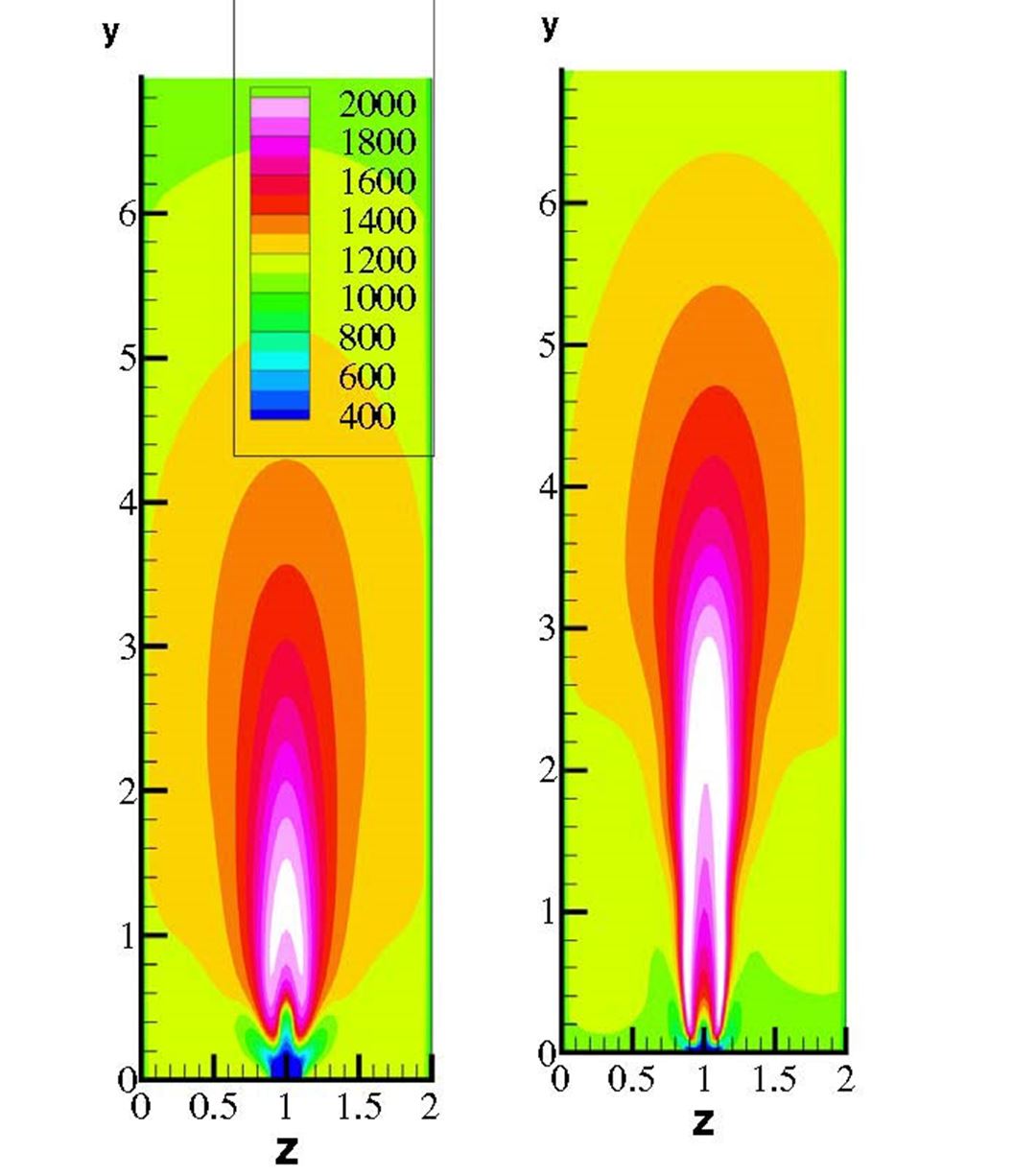
- Numerical simulations performed that showed the potential for retrofitting existing furnaces to H2 combustion. The results indicate that, contrary to expectations, NOx emissions are reduced or remain the same. This has been preliminary verified in lab experiments. Detailed lab testing is ongoing.
Integrated assessment
Overall objective:
To evaluate the potential of CO2 capture technologies (solvents, sorbents, membranes) and, based on unit modeling and process simulations, point out the direction for further research on these capture technologies.
Contribution to one or more of the overall goals/objectives of BIGCCS
The conclusions from task 1.6 research have throughout the lifetime of BIGCCS been directly comparable to the tangible objectives of 90% CO2 capture rate and fuel-to-electricity penalty of 6 percentage points. Beginning from 2014, increased focus will also be on the requirements that must be put on CO2 capture for achieving a 50% CO2 capture cost reduction compared to most mature technologies.
Task 1.6 achievements thus far:
- Investigation of different means of CO2 enrichment in the exhaust of gas turbine-based power processes, including collaboration with Task 1.4 on gas turbine combustion with low oxygen concentrations.
- Investigations of calcium looping (Ca-looping) for post-combustion capture in natural gas combined cycles (NGCC). A systematic approach has been employed where different measures for process efficiency improvement have been applied, covering both power process and Ca-sorbent improvements. The best cases reach an electric efficiency penalty of around 6%-points, i.e. they respond to one of the BIGCCS objectives.
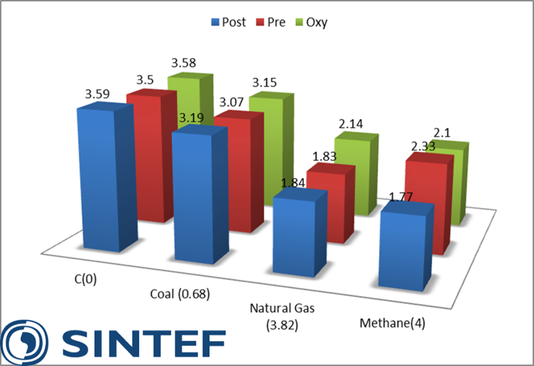
- The fundamental calculations for a novel thermodynamic benchmarking methodology have been conducted, meaning that the inherent thermodynamic penalties of CO2 capture have been determined (figure 1). The pillars in figure 1 show the minimum penalty for different CO2 capture routes and different fuel compositions imposed by the laws of thermodynamics. In addition to these penalties come the penalties imposed by technological constraints (e.g. materials limitations, process unit irreversibilities) and those imposed by economic constraints.
Looping technologies
Overall objective:
To increase the knowledge and technology basis in CLC reactor system design and oxygen carrier material development in order to bring CLC technology to the next level of maturity.
Contribution to one or more of the overall goals/objectives of BIGCCS
Recent studies indicate that one of the main benefits with CLC technology is the potential low CO2 capture efficiency penalty. As such, it contributes directly to one of the main objectives of BIGCCS which is to develop knowledge and technology with potential of penalty less than 6 %-points.
Task 1.7 achievements thus far
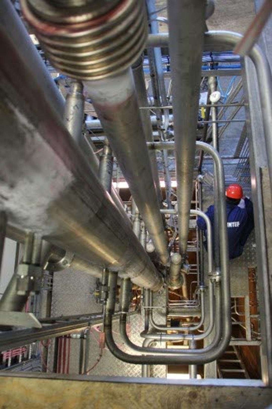
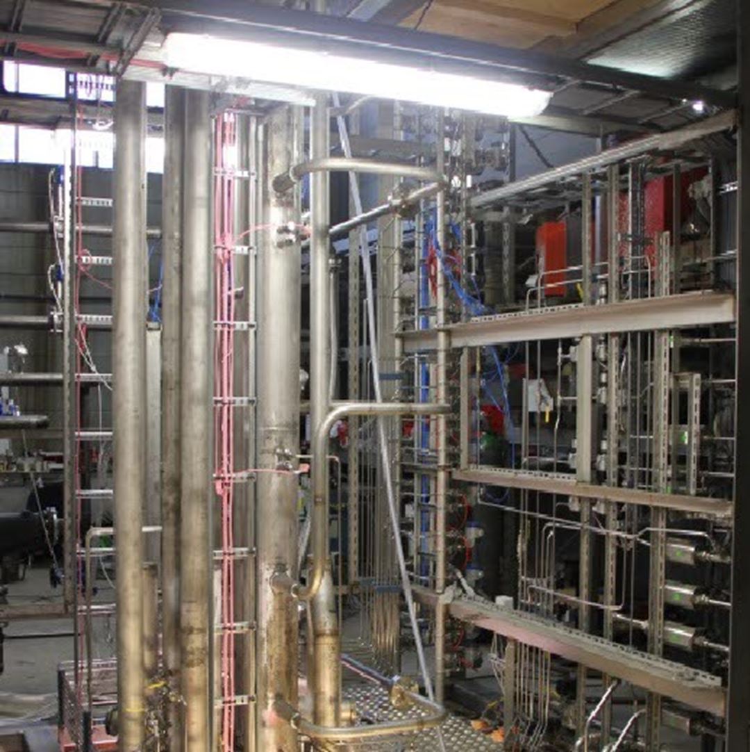
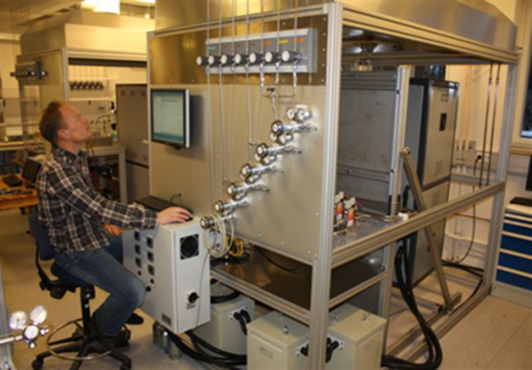
Based on material screening and testing the task has recommended an oxygen carrier material based on manganese oxide and calcium to be developed further within the project. The task has acquired flexible equipment for oxygen carrier particle production which is being used to formulate optimal production methodology. A fluidized bed reactor of about 3 kW power has been developed, specifically to be used for the first testing of new oxygen carrier materials. At a larger scale, of about 150 kW, the project has developed and built a second-generation fluidized CLC reactor system aiming at high fuel conversion and operational flexibility. At this size, results will be more realistic and contribute to higher confidence before technology up-scaling.
Related publications
- NGCC post-combustion CO2 capture with Ca/carbonate looping: Efficiency dependency on sorbent properties, capture unit performance and process configuration
David Berstad, Rahul Anantharaman, Richard Blom, Kristin Jordal, Bjørnar Arstad | | 2014 - Double loop circulating fluidized bed reactor system for two reaction processes, based on pneumatically controlled divided loop-seals and bottom extraction/lift.
Bischi, Aldo; Langørgen, Øyvind; Bolland, Olav | | 2013 - Studies of Ca-based high temperature sorbents for CO2 capture
Arstad, Bjørnar Spjelkavik, Aud Andreassen, Kari Anne Lind, Anna Prostak, Joanna Blom, Richard | | 2013 - Hydrodynamic viability of chemical looping processes by means of cold flow model investigation
Bischi, A. Langørgen, Ø. Morin, J.-X. Bakken, J. Ghorbaniyan, M. Bysveen, M. Bolland, O. | | 2012 - Continuous hydrogen production by sorption enhanced steam methane reforming (SE-SMR) in a circulating fluidized bed reactor: Sorbent to catalyst ratio dependencies
Arstad, B. Prostak, J. Blom, R. | | 2012 - Design study of a 150kWth double loop circulating fluidized bed reactor system for chemical looping combustion with focus on industrial applicability and pressurization
Bischi, A. Langørgen, Ø Saanum, I. Bakken, J. Seljeskog, M. Bysveen, M. Morin, J. X. Bolland, O. | | 2011
